Gear linkage
The gear
linkage uses a Mini rod change remote turned through 180
degrees.
The gearlever, gearlever locating pin and the base plate of
the remote are also reversed.
The remote bolts solidly to a bracket on the chassis.
(The rest of the linkage/cranks ensures that the standard
'H' gear selection pattern is maintained).
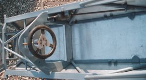
The remote change fits to the right of the steering wheel, the gear lever has been shortened to about 5 inches by cutting off the rubber bushed portion and attaching a gear knob to the remaining stub. Some bending of this stub was required and as this piece is very hard some cracking had to be welded after bending.
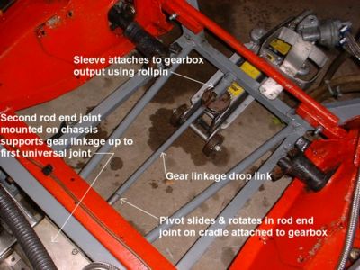
The rod from
the remote is supported by a rod end behind the seat, this
rod is connected to a universal jointed shaft
(a lengthened Fiat 127 steering column section) which moves
the linkage to the centre of the chassis.
The linkage then passes through a pair of rod end joints,
one mounted on the chassis and one mounted on a cradle
attached to the gearbox.
Attached to
this last section is a drop crank of 2.5 inches which takes
the link, underneath the gearbox,
to the rear rod change input shaft.
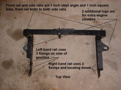
To ensure that gear selection is consistent, it is necessary
to adequately support the engine/gearbox and the remote to
avoid 'lost travel' in the gear linkage.
I have added two lower engine steadies which attach to the
gearbox cradle and run forward to the chassis at either side
rails.
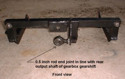
Gearbox cradle
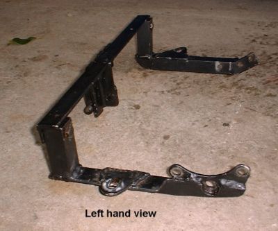
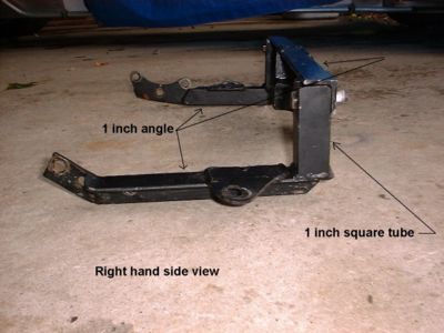
Drop link