Mini (front)
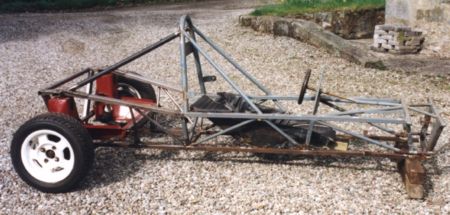
subframe & suspension installed in rear of chassis.
To stop the hubs steering at the back, the existing steering
track rods have had a second set of track rod ends fitted
inboard and attached to the subframe.
Wheels (5" x 12") have been borrowed from my Mini for the
photo.
Actual rear wheels are 10" x 13" shod with Avon 9.0 x
20.0-13 Slicks.
Fronts are 8" x 13" with Avon 7.2 x 20.0-13 Slicks.
As the slick tyres I have are very old, I will probably
replace them with new slicks when funds allow.
The rebuild has been going very slowly during the summer of 1999, I keep being distracted by other pursuits.
October
1999 - I managed to acquire a set of old Dunlop FF1600
tyres and rims. These will do as a set of wet weather and
storage tyres. The FF1600 rims fit the front hubs (Triumph
stud pattern I believe).
I will need to get some 4" PCD wheels (5.5 or 6 x 13) for
the rear.
For the slick tyres, I have two 10" x 13" and two 8" x 13"
(4" PCD) Revolution split rim wheels - these will do for the
rear. For the front I will have to source some 8" x 13"
wheels to suit the FF1600 hubs.
November 1999 - I have at last got round to fitting
the engine steady mounts and fabricating a gear linkage.
The gear
linkage
uses a Mini rod change remote turned through 180 degrees.
The gearlever and the base plate of the remote are also
reversed. (The rest of the linkage/cranks ensures that the
standard 'H' gear selection pattern is maintained).
The remote change fits to the right of the steering wheel,
the gear lever has been shortened to about 5 inches.
The rod from the remote is supported by a rod end behind the
seat, this rod is connected to a universal jointed shaft (a
lengthened Fiat 127 steering column section) which moves the
linkage to the centre of the chassis. The linkage then
passes through a pair of rod end joints, one mounted on the
chassis and one mounted on a cradle attached to the gearbox.
Attached to this last section is a drop crank of 2.5 inches
which takes the link, underneath the gearbox, to the rear
rod change input shaft.
To ensure that gear selection is consistent, it is necessary
to adequately support the engine/gearbox and the remote to
avoid 'lost travel' in the gear linkage. Sitting in the car,
I appear to have all the gears in the right places and they
are easily selected. The travel in the gear lever is just
right and the gearknob is nicely positioned with respect to
the steering wheel.
My next task is to fabricate a new pedal box to mount the
master cylinders (The old one was a bit bent and the cutouts
for the master cylinders do not match the new type). Which
reminds me that I must order a pair of .625" bore master
cylinders, with integral reservoirs, from Merlin
Motorsport,
I shall also have to order a new 6 point safety harness at
the same time.
December 1999 - I have now received my master cylinders (from Demon Tweeks). I also got a pair of 90 degree, 1 3/4" dia., mandrel formed, exhaust bends. These have been welded to an RC40 silencer which is mounted across the rear of the chassis. The silencer connects to a Maniflow 3-branch Mini exhaust manifold which has had its bottom bend turned by about 45 degrees to allow a 45 degree elbow to turn the exhaust parallel to the rear of the chassis. I will need to provide some sort of heatshield to avoid burning anyone who gets too close to the silencer (and to avoid boiling the petrol in the carbs). I will probably use exhaust wrap on the manifold as well.
I have folded up a new sheet metal, mounting plate for the master cylinders. I still have to drill the plate (I now have a 30mm hole saw to make the cutouts). On pulling the pedal assembly out of the garden shed, I found that one of the clevis ends for the brake balance bar was missing, so I am getting a new one machined by a local, friendly, machine shop.